But what is the suspension of a car? To keep it short, we could define it as everything that connects the wheels to the rest of the car. And as such, it is of vital importance as we will see below. Let's make a summary of the types of suspension and their main design parameters, trying not to leave anything important out. Let's start.

Suspension objectives
The suspension of a car in general must meet several objectives, such as maintaining ground clearance, providing comfort to the occupants, having predictable reactions, maintaining the optimal angle of the tire to the road in any circumstance (acceleration, braking, cornering, pothole or speed bump, or any combination of them) and optimizing the available traction, taking into account the type of tire to be used. Not bad for a single system.
But of course, this hasn't always been the case. Looking back to the origins of the automobile, the suspension had a minimum objective of keeping the car stable, with a minimum of comfort. Do you know the leaf springs? They were the only elastic element to be used in the early years, inherited from carriages, together with the rigid axle, due to their low cost, simplicity and durability.
Although it had already been invented for many years, it was not until 1934 when the manufacturing techniques of coil springs were refined. It was then that they began to be fitted in cars, together with the new hydraulic shock absorbers. The modern era of suspension began.
As you can understand, if you design something with several goals in mind, the word that floods the minds of engineers is "compromise". It's obvious that you can't design something that will be great, meeting all the goals at the same time. There will be goals that predominate over others, depending on what the brand wants to achieve (sedan, utility, sports car, supercar, racing, etc.).
Types of independent suspension
We are now going to make a quick review of the types of suspension that exist, leaving aside the rigid and semi-rigid suspensions. Although they are still used today (especially in the rear due to their low cost, space and simplicity, see Opel Astra with De Dion axle, Renault Talisman, Peugeot 308, and many other A and B segment cars), we are going to focus on independent suspensions, as they are the ones that offer the greatest dynamic benefits.
- Oscillating axle. This is basically a rigid axle, with articulation on the axle shaft.
- Pulled arms. Used in rear suspension, it was one of the most basic independent suspensions, and used in many vehicles (Citroën 2 CV, for example). It has an arm, with an axle at the front, which performs a semicircular movement in the suspension travel.
- Semi-pulled arms. It is a variation of the pulled arms, which provides greater rigidity to the suspension during transverse forces.
- Weissach. This is a variation of the semi-pulled arms used in the Porsche 928. It has the advantage of correcting oversteer by changing the toe in compression (more on this later).
- McPherson. Perhaps the most used and most successful suspension in automotive history, thanks to its simplicity and low cost. It consists of a lower arm and a rigid column, with upper pivot. It is usually used as front suspension. Although there is a very coveted car, which has McPherson both front and rear. Do you know what it is? Porsche Cayman.
- McPherson strut uncoupled. It is a variation of McPherson, which has some advantages over its design, improving some parameters over the traditional McPherson. Nowadays it can be found in some Ford and GM sport models.
- Double arm. Also called trapezoidal or overlapping triangles. It is very common in both axles, especially nowadays, both in street cars and competition cars. Although it is somewhat more complex, expensive and steals a lot of space, it allows a more precise design of the wheel angles.
- Multilink. It is a variation of the double arm suspension, in which 5 independent arms are normally used (can be more), to achieve the optimum wheel angles according to the designer.
As we can see, the more complex a suspension is, the more degrees of freedom it has to perform the function we want. Although its design and packaging becomes more complex.
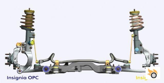
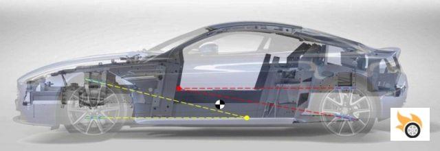
We talked a few lines above about optimal wheel angles. What is this? We are going to focus on a double arm suspension, as it is the most versatile. The rest of the suspensions have the same parameters that we are going to see below, although the way to visualize and calculate them varies.
Parameters of a suspension
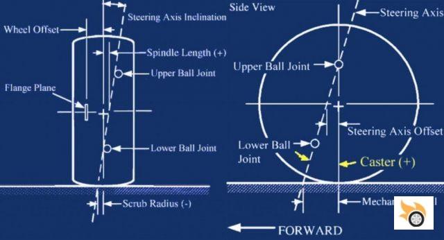
In this picture you can see a summary of all the important parameters, which we can call wheel angles, which we will talk about later. The hard points or anchor points to the chassis are missing, which are also very important, because they determine the length of the arms and their angle to the ground.
The distance of the arms is responsible for the wheel drop varying in compression or extension. This is why the upper arm is shorter than the lower arm. In order to achieve a negative camber in compression and a neutral or slightly positive camber in extension. If the arms were of equal length and parallel, the wheel would always move vertically, which would not be desirable in a curve. When the chassis is tilted, the outside wheel would have a very positive camber when turning, while the inside wheel would be very negative. We will see it in depth later.
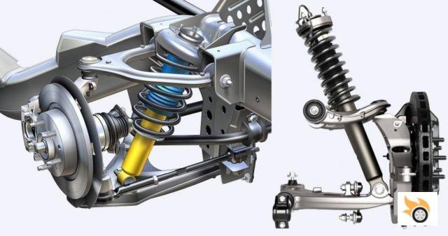
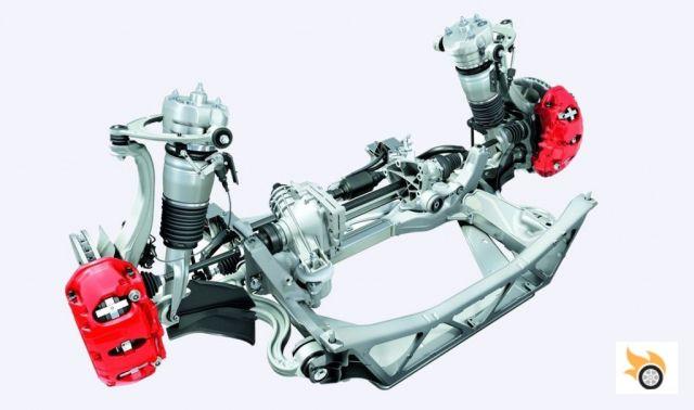
But first let's see what parts a double wishbone suspension has. The components, in short, are usually the following:
- Knuckle (knuckle, spindle or upright). This is the metal part to which the bearing, brake disc, brake caliper, wheel and three ball joints are anchored. This will allow the wheel to articulate when we turn the steering. There may be more exotic arms, with double ball joint arms, or H-shaped arms.
- Upper Control Arm. It is the upper triangle of the suspension. Two of its points are anchored to the chassis. And the other to the upper ball joint of the stub axle.
- Lower Control Arm. Longer than the upper arm, it also has two anchorages to the chassis, and the other to the lower ball joint of the stub axle.
- Steering link (Steering link or Tie-rod). The steering arm is responsible for turning the wheel on its pivot axis. It is anchored to the stub axle with another ball joint. If it is the rear suspension, it is usually called Tie-rod as it is responsible for maintaining the toe-in, within the design parameters, during the suspension travel.
- Spring-shock absorber assembly (Coil-Damper). It is generally attached to the lower arm. Although you can find suspensions, where the attachment point is the stub axle or upper arm. Depending on where this joint occurs, it will result in a different motion ratio.
- Stabilizer bar. Normally anchored to the lower link, to act in roll, equalizing both sides and reducing roll.
Let's see the fundamental parameters in detail.
Travel and ground clearance
The first thing to be clear about is the suspension travel in compression (-) and in extension (+). This parameter can range from ±15mm in Formula 1 to ±100mm in an off-roader. Sometimes it is asymmetrical, having more extension than compression; or the other way around. Even the front suspension travel is different from the rear. Let's look at some simplified examples of travel:
- Formula 1: ±15 mm
- McLaren F1: ±80 mm
- Lotus Elise: ±50 mm
- 2004 Subaru WRX STI: +95/-75 mm
- Trophy Truck: ±760 mm
Ground clearance is the next design parameter. We will see that here not only the geometry influences, but also the spring: harder, means that the car lowers less when supporting its own weight. But the harder the spring, the worse the road behaviour. Remember the word "compromise" that we mentioned at the beginning. Some examples of ground clearance:
- Formula 1: 32 mm
- McLaren F1: 119 mm
- Lotus Elise: 130 mm
- Ferrari 355: 163 mm
- Ford Raptor: 241 mm
Arms: Length, Angle, relative distance
To determine the length of the arms, we must know in advance what track width we want, what is the necessary space for the engine and other components. This way we can know how much space is left to place the suspension. This in itself is an important restriction. What length of arms do we choose? Well, the longest possible, within our restrictions, as long as the angles we want are met. There is no universal rule, and it is more a matter of trial and error with the simulation software, to get the optimum wheel angle during the suspension travel.
As a quick rule of thumb, you can say that the lower arm is twice the length of the upper arm. Remember that we want the wheel to have negative camber when compressed, and neutral or slightly positive camber when extended. The upper arm will have a certain angle towards the center of the car. And the lower arm will maintain an angle close to zero. The position of the arms will determine the following angles that we will talk about.
Scrub radius (scrub radius)
To find out how much scrub our design has, we will draw a line joining the upper and lower ball joint (pivot axis), until it cuts the ground. If the cut is on the outside of the center of the wheel, we will say that the scrub is negative. If it cuts right in the centre of the wheel, the scrub will be neutral. And if it cuts towards the inside of the wheel, the scrub is positive. You can go back to the photo of the wheel angles to visualize it. I'm sure you're wondering, what does the scrub influence? Well, in short, it influences the sensitivity of the car, how the steering "speaks" (torque steer, or that the steering gets the car into the curve). A negative scrub makes it less sensitive to variations in the wheel (puncture, loss of pressure, pothole, etc.). A positive scrub, on the other hand, will make you more sensitive to what is happening between the wheel and the road. Generally, any car equipped with McPherson struts has negative scrub. That is, almost all cars that we mere mortals use go like this.
Some examples:
- McLaren F1: +16.25 mm
- Lotus Elise: +10.5 mm
- Corvette C5: +10 mm
- Mazda MX5: 0 mm
As you can see, sports cars usually use a slight positive scrub, to increase the steering sensitivity.
One detail: the scrub can be changed. Since it is related to the center of the wheel, by changing the wheel offset, we can change this radius. In other words, if we change the offset of the rim on a car with a negative scrub, we will be changing the scrub. That is why it is important to stick to the rim sizes specified by the manufacturer. Changing the width of the tyre will not affect this, as the centre remains in the same place.
Kingpin axis (Kingpin axis)
The kingpin axis is nothing more than the line that connects the upper ball joint to the lower ball joint. This axis will have some inclination, as the upper arm is shorter than the lower arm. Again, depending on its inclination (KPI), the wheel will transmit more or less feedback forces to the steering (see picture). As for example:
- Ferrari 355: 13.16 º
- Lotus Elise: 12.0 º
- Mazda Miata: 11.3 º
- Ford Mustang: 11 º
- Lotus 7: 9th
- McLaren F1: 9th
- Corvette C5 and C6: 8.8th
- Triumph Spitfire: 7th
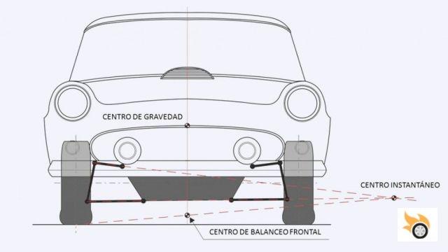
Roll center (roll center)
Let's now with the roll center. To calculate it graphically, we make a line joining the two points of the upper arm, and another for the lower arm. This gives us a point on the outside of the car, which is the instantaneous center. Now we join this instantaneous center with the center of the wheel. The point where it cuts the central axis of the car, that will be our roll center. Why is it important? Because it will be the point on which the car turns when cornering. Since the rear suspension also has its own, by joining the two we get the roll axis.
Its position relative to the centre of gravity is also important. If they both coincide, the car would not lean. But the suspension would not work. Therefore, as a general rule, it should always be below the centre of gravity, and above ground level. And the front should be lower than the rear, to give more safety and confidence to the driver.
As you are pistonheads, some of you may have read that in Formula 1 the "roll center" is located below the ground. It's something anomalous, that doesn't hurt much to have such a low centre of gravity, as they have other more important criteria to take care of.
Example:
- Lotus Elise: front roll center 30mm - rear roll center 75mm.
- Mazda RX8: roll center front 68mm - roll center rear 96mm
Tilting the suspension arms towards the center of the car, moves the roll center up. If you look at any car from behind, and look at its lower arm, you will see that the suspension arm points upwards, i.e. the inner anchor point is higher, than the anchor point on the wheel.
Track width (Track width)
Now we have to go back to the word "compromise". I explain why. Many times, when designing a suspension, all the angles fit what we want, but when raising and lowering the suspension, the wheel does not stay in the same center, it moves left and right a few millimeters. What does this produce? An increase in tire wear. Depending on how many millimeters it is, it can be acceptable or not. The values are usually ±8mm. More of this, we are going to "eat" the tyres quickly.
If you look at Formula 1 again, there are teams that wear the tyres very quickly, and others that keep them intact for many more laps. One of the parameters that influences (but not the only one), is this. If you are a fan, keep an eye on what happens this weekend at Spa.
Camber
The camber is the inclination of the wheel with respect to the chassis. We have two types: static camber and dynamic camber.
The static camber is usually an adjustment parameter for the test drivers of a brand. It is usually small, in the order of -1 º, and can be different at the front and rear.
The dynamics is fixed by the design of the suspension. As we said before, when the wheel goes up (bump), the ideal is that the drop is negative, that is, that the top of the tire points towards the center of the car. This makes the tyre work better, keeping more surface in contact with the road, compensating the inclination of the chassis when cornering. When going down (speed bump) the ideal is to keep it neutral, or to have a slightly positive camber (pointing the top of the tyre towards the outside of the car).
To give you an idea, these drops are a few degrees. In compression it is usually -3 to -5º. And in extension from 0 to +2 º. As an example, the static drop of a Formula 1:
- F1= -3º at the front, -1º at the rear.
What happens when we place shorter springs to lower the car? We are completely altering the midpoint of the suspension, losing travel in compression, and increasing the static camber.
This camber can also be changed by turning the steering, thanks to the following parameter that we will see next.
Caster
If you look at the picture of the wheel angles, the right side represents the wheel seen from the side. It is nothing more than the inclination of the axis of rotation of the wheel. Very similar to the wheels of the supermarket trolleys. If the top is closer to the center of the car, the caster is said to be positive. If it is the other way around, it is negative.
In the car a slight positive caster is used, in the order of 4º to 6º. And what does it influence? What the caster does is to produce a positive camber to the wheel that is on the inside of the turn, thus compensating for the inclination of the chassis in the curve, and making the wheel remain as flat as possible on the road.
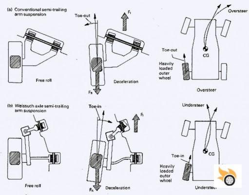
Toe
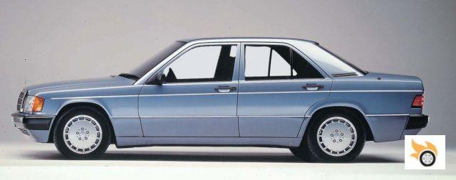
To talk about toe in, let's look at the image of the Porsche 928 Weissach suspension. It is a view from above. Positive toe in is when the front of the wheel points to the inside of the car. It will be negative (toe out) when it points outwards. And it will be neutral or zero when the wheels are aligned.
As with camber, we can have static and dynamic toe in. Almost all cars have a slight positive toe in the front axle, to compensate for drag in motion. In this way, when in motion, the wheel is perfectly aligned with neutral toe-in.
By adjusting the length of the steering arms (Tie-rod) we can induce positive or negative toe-in when the suspension is compressed or extended. This is what Porsche did with the Weissach suspension. When the rear wheel is compressed, it has positive toe-in, helping the car to turn. Some of today's models also have this "help" to turn. If you allow me, here I'll give my opinion: I don't like toe-inducing suspensions. I prefer zero toe-in suspensions. They do the work of suspension. For turning, there is already the steering. From my point of view, when a suspension changes toe in compression or extension, it means that it "covers up" some other defect in the car's dynamics.
Anti-squat (anti dive, anti squat)
Most of the cars with sporty character, have among their design parameters the anti-squat. Those of Shakespeare's language call it "anti dive" when braking, and "anti squat" when accelerating. What they try to achieve is to transmit some percentage of the force to the suspension arms, so that the nose doesn't sink so much under braking, nor the rear under acceleration. How is it achieved? If you look at the picture I took for the occasion, the front upper arm (blue) is tilted backwards. With this we get the "anti dive". How much we want, will depend on where the lines are cut, with the axis of the center of gravity.
At the rear, on the other hand, the lower arm is tilted. As in the front, the greater the angle, the greater the "anti squat". But you have to be careful: too much would cause strange behaviour in the suspension.
To see it "live" is difficult, because you would have to remove the wheels to see it.
Spring-shock position
Well, we already have the suspension designed. Now we have to place the spring-shock assembly. Where do we put it? In a quick way, we can say that we draw a line from the center of the wheel (where the forces come from), to the upper anchor point of the shock absorber. Where the lower arm cuts that line, will be the anchor point. It will always be less than the length of the lower link. That's why we define the motion ratio, which is nothing more than dividing the distance from the chassis to the shock anchor point by the length of the lower link.
Why do this? Remember the law of leverage. This ratio will help us in the following points.
Spring choice: natural frequency and motion ratio
Let's go now to the springs. Knowing what kind of car we are designing, we will choose comfort or sportiness. To do this, we will define what natural frequency we want. What is that? To be brief, it's nothing more than how many times per second a suspension oscillates naturally. In other words, it is something inherent to its design. To do this, let's look at some examples of natural frequency (1 Hz = 1 oscillatory movement per second):
- Normal saloon < 1.3 Hz
- Sport sedan: 1.3 Hz - 1.5 Hz
- Sports car: 1.5 Hz - 1.8 Hz
- Supersport car: 1.7 Hz - 2.0 Hz
- Rally car (asphalt): 2.2 Hz - 2.6 Hz
- Formula 1: 4.0 Hz - 6.0 Hz
The higher the frequency, the firmer the suspension. What would happen if the front and rear suspension had the same frequency? When going over a bump or speed bump, the whole car would oscillate at the same frequency, producing a resonance effect, which could cause dizziness in the occupants. Let's remember that continuous oscillations of 1 to 2 Hz tend to make us dizzy. For this reason, a different frequency is usually selected for each axis. And we return to the "compromise". Depending on whether we want to print an understeer or oversteer character, we can play with the front-rear hardness. Softer at the front, more oversteer. Some examples:
- Mazda RX-8: 1.38 Hz front / 1.47 Hz rear. Diff: 6.5%.
- Lotus Elise: 1.50 Hz front / 1.63 Hz rear. Diff: 8.6% Diff: 8.6% McLaren F1: 1.50 Hz front / 1.63 Hz rear
- McLaren F1: 1.41 Hz front / 1.75 Hz rear. Diff: 24.1% Diff: 24.1% BMW M3: 1.26 front / 1.75 Hz rear.
- BMW M3: 1.26 in front / 1.48 Hz in rear. Diff: 17.4% Diff: 17.4% Corvette C5
- Corvette C5: 1.20 Hz / 1.45 Hz rear. Diff: 20.8% Diff: 20.8% Diff: 20.8% Diff: 20.8%
Having the frequency we want and the motion ratio it is very easy to calculate the spring hardness needed. Important: the suspension travel. We will have to make sure that the spring has enough length to assume the full travel of the suspension.
As you can see, everything is interrelated, so we must be especially careful when tuning, lest we worsen some of the parameters of the suspension.
Choice of shock absorber
This point could be the subject of a whole book. It is really complex and very dependent on what we want to achieve. As we are not going to go into it in depth, we are going to give some average values about the damping coefficient (it is nothing more than the speed at which the oscillation decreases):
- Comfortable saloon: 0.3
- Sport: 0,5
- Competition: 0,7
As with the spring, it is important that the shock absorber travel supports the full travel of the suspension, plus a safety margin, so that it does not reach its limit and may affect the structural integrity of the shock absorber itself.
Choosing the anti-roll bar
To choose the anti-roll bar, we must take into account the character of the car. Generally, and to begin with, it is usually chosen with a hardness similar to that of the springs of that axle. Afterwards, with the dynamic tests, the value can be adjusted to bring the behaviour to where we want it to be.
Active suspension
At this point we are going to reflect some exceptions to the conventional design that we have tried to explain. And that are quite important nowadays, since they allow to change certain parameters of the suspension on the fly.
- Air springs. Rubber springs, filled with air, which can be adjusted, filling or emptying them with air, to vary the ground clearance.
- Variable shock absorbers. Here there are many types, from those used by Citröen, those used by McLaren, to magnetorheological ones. They vary the damping coefficient in real time (automatically or by driver selection), through different techniques, to offer a more comfortable or sporty behaviour.
- Active stabilizers. Currently widely used, there are different approaches. Some manufacturers use an electric motor to twist the bar (Audi Q7 2016). Others use hydraulics (Porsche PDCC, BMW Dynamic Drive), and others use a passive hydraulic system, to disconnect the bar when it is not necessary (Toyota Land Cruiser).
Finally, a curiosity. There is a quite interesting suspension scheme, totally passive, but that achieves something quite commendable: it keeps the wheel perpendicular to the road, in any circumstance, interconnecting the suspension on one side with the other, through arms that pivot on different axles. Its name, CC&AR.
If you want to play with designing a suspension, there is a free website that helps us in a simple way: Racing Aspirations.
As we have seen, the design of a suspension is something very complex that involves many premises and compromises to be fulfilled. It is very difficult for a brand to achieve the perfect balance of all the variables, to obtain a good dynamic behavior that satisfies the majority. In the end, all that design, formulas, numbers and diagrams boils down to one thing: to get a smile on our faces when we link one curve after another. That's why we're pistonheads.