Why it is necessary
Let's start by clarifying that the differential is only necessary on the drive wheels, as they are the ones that drive the car, and therefore the ones that need torque to transmit to the ground.
Let's imagine that we have a car without a differential, i.e. the two driving wheels are rigidly connected (like a go-kart). We are driving in a straight line at a constant speed, the wheels are turning normally, and on the left side we find a small speed bump. Let's look at the drive axle: the left wheel will travel a few centimetres further than its companion, as it has to go up and down to negotiate the bump. What happens? The right wheel, as it travels less distance, will be further forward than the other, causing a small torque to the left. Therefore, we are faced with a vehicle that does not have good linear stability.
We already sense that some mechanism is needed to remedy this. Looking at the following example, we will be convinced that it is essential. Let's imagine the vehicle from before, negotiating a curve. Since the outer wheel (l2 in the photo) must travel more meters than the inner wheel (l1 in the photo), and the wheels are rigidly connected, one of them must slide to maintain the rotational revolutions of the wheels. Bad thing, because we provoke a tremendous wear of the tyre, and the stability in curve is not going to be good at all.
To solve these two fundamental problems the differential was born.
A bit of history
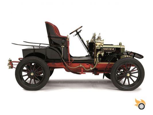
Back in 1876, bicycles were in their infancy. Their designs consisted of a huge front wheel and a very small rear wheel, which made them difficult to use: it was difficult to get on and off them, not to mention the strange handling of the steering with those big wheels.
In Coventry (UK) a man named James Starley decided that what was needed was to redesign the bicycle, so that anyone could get on and off it easily. That's how he came up with his tricycle (you can see a picture of James with his invention). He put two big wheels at the back, a small one at the front, and a comfortable enough seat for pedalling. To the bottom bracket axle and its sprocket, he geared a chain that propelled the rear axle with a sprocket. A revolution in bicycle design at the time. When he built his first prototype and went out to test it, he immediately realized that something was wrong: the tricycle was difficult to control in straight lines, and in curves it was so hard to pedal that it was unable to move forward.
James, being a good Coventry Englishman, went to the pub in the evening to think about the cause of his trike's problems. After a few pints he discovered the fault: the two rear wheels, being connected by a rigid axle, could not corner properly because of the different distance each wheel travelled. It was necessary to intercalate between them some mechanism to compensate the turning radius of the outer wheel compared to the inner one.
After several weeks of thinking about it, he finally had a brilliant idea and built a prototype. He immediately mounted it on his tricycle and when he tested it he was amazed with its behaviour. He had just invented the open differential. Thus, when pedalling, the differential compensated for the different distances travelled by the wheels, even when cornering.
Ten years later, when Karl Benz was building the first car on the planet - actually a motorized tricycle - he included Mr. Starley's invention. That would be the first car to mount a differential.
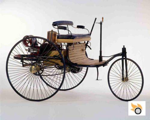
Some historians indicate that who really invented the differential was Onésiphore Pecqueur in 1827, although it should be noted that the differential mechanism in astronomical clocks dates back to 200 BC as used in the mechanism of Antikythera. What is clear is that James Starley was the first to apply it in a vehicle.
In the years that followed, engine power increased, and Starley's differential could not withstand so much torque, so some manufacturers decided to build cars without a differential. How is this possible? By simply putting the drive to only one rear wheel. That way, the other wheel turns freely, and there are no problems of decompensation in turns; but this solution proved to be inefficient, especially on dirt roads, quite abundant at the time, thus decreasing traction, and making it very difficult to move forward.
This is where the Packard Motor Car Company of Detroit came in, perfecting Benz's design, and making the first bevel gear differential in 1913. This made for a smoother transmission of power, as well as quieter. In 1926, Packard introduced the hypoid gear (nothing more than a bevel gear shifted downwards), with which we are still using today. This allows the driveshaft that connects the gearbox to the differential to be lowered, so that it is less intrusive in the passenger compartment. Virtually all rear-wheel drive vehicles have a hypoid gear differential. On front-wheel drive vehicles, the reduction is done with a single pair of gears.
In 1958, Vernon Gleasman patented a new differential, which improved the properties of the open differential: the Torsen limited slip differential was born. We will look at these types of differentials and their functions in more detail later.
Location
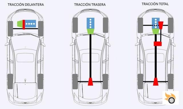
Before we continue, let's visualize where the differential is located. Depending on the type of traction the car has, we will have from one to three differentials. In the image we have represented the three most common types: front, rear and total. Within these there may be variations, such as a car with front transverse engine with all-wheel drive (Ford Focus RS, Audi RS3), one with longitudinal engine and gearbox that incorporates the transfer case, center differential and front (Subaru WRX, Audi RS4), etc.. For simplicity we will focus on the three in the image.
We have represented the engine in blue, gearbox in green, driveshafts in black and differential in red.
In a vehicle with front-wheel drive and transverse engine (most of those currently on the market), the differential is located between the engine and the gearbox, but behind both. In this configuration the reduction gear is not hypoid, but a simple pair of gears, such as those found in the gearbox. That is, two gears of different diameters.
In a rear-wheel drive vehicle, the differential is connected to the gearbox via the drive shaft. In this case we find that the reduction gear is hypoid.
In an all-wheel drive vehicle we will have three differentials: the central one, which is responsible for dividing the torque between the front and rear axles; and a differential on each axle, to distribute the torque to each wheel. Added to this, a central transfer case is needed, to distribute the torque to the front axle, which usually has no reduction, so the gears will be the same size. Normally, the packing is quite complicated in this configuration, so in many occasions one of the front axle shafts has to go through the engine oil sump, in order to get to the other side. That's why we have put a dashed line in the picture.
Depending on whether the differential is central, front or rear, the manufacturer will choose one type or the other, as their qualities vary.
Since it is very complicated to understand it in a static way, reading and looking at a photo, I attach a video of 1937 that even being very old, I think it is by far the clearest in the explanation:
Parts of a differential
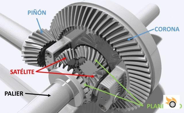
In the image below you can see an open differential -the one mounted in most cars- of a vehicle with rear drive axle.
In blue we see the reduction gear, formed by the pinion which is attached to the drive shaft coming from the gearbox, and the ring gear, which is attached to the differential. This is the hypoid gear (the longitudinal axis of the pinion does not coincide with the centre of the ring gear). What is this gear necessary for? To change the direction of the force by 90º and to adapt the rotation of the motor to the rotation speed of the wheels. We will see this in detail in the next point.
The parts that perform the differential function as such are the satellites (red) and the planetary gears (green). The planetary gears are rigidly attached to the bearings that transmit the power to each wheel, while the satellites rotate freely on their axis. One of the planetaries will always be attached to the crown wheel, being connected to the other planetary by means of the gearing with the satellites.
Later we will try to explain what function each part performs.
Reduction gear
Let's now take a look at the reduction gear - pinion and crown in the picture - and why it is necessary. The best way is for us to use an example. Let's do some simple calculations, approximating to round figures so as not to overcomplicate it.
Let's suppose we drive our car with 205/50 R17 tyres, in fifth gear at 120 km/h, with the engine running at 3000 RPM. Let's assume that the development of fifth gear is 1:1, a direct one. At how many revolutions per minute are the wheels turning?
Let's do some quick calculations to find out. First we calculate the length of the circumference of our wheels. The radius of those tires is approximately 31.2 cm. So, if we multiply by 2 and by π we get a result close to 2 meters. Therefore, with one complete turn of the wheel we advance 2 meters. Now we change the units of the speed: 120 km/h is about 33 m/s. Almost there.
If we divide the speed, by the length of the circumference of the wheel, we get the rotation frequency in Hertz (cycles per unit time): 33 m/s by 2 m gives us a result of 16.5 Hz. As 1 Hz is one revolution per second, just multiply by 60 seconds to get the revolutions per minute. The result is that the wheels turn at 1,000 RPM.
Let's recap: we have the engine turning at 3,000 RPM; the gear ratio is 1:1, so the driveshaft is also turning at 3,000 RPM; but the wheels are turning at 1,000 RPM. What do we need? A reduction gear that adapts both rotations. If we divide the engine rotation between the wheels, we get a ratio of 3:1. That is, the ring gear will have three times as many teeth as the pinion. A reduction ratio of 3:1 is quite common, although it is variable depending on the characteristics of each motor-gearbox pair.
Knowing the reduction ratio, the size of the wheels, the gear ratio and the maximum engine rotation, we can calculate the theoretical maximum speed that a car can achieve, if it has enough power, we can't forget about aerodynamics. Therefore, if we change the standard tyres for others of a different size, we must be careful with the choice so as not to alter the final development.
The reduction gear, although it is packed inside the differential case, should not be confused with the differential itself, as it has a different function, which is to adapt the rotation of the engine to that of the wheels.
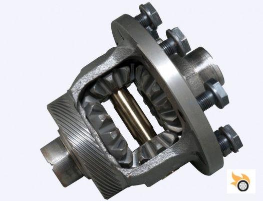
How it works
In the picture you can see an open differential, which we are going to take as an example because it is the most common. The crown of the reduction gear would be placed on the left side, where the threaded holes are. Therefore the whole differential block rotates together with the crown wheel. If both wheels rotate at the same speed, the planetary gears will rotate at the same speed, and consequently the satellites will remain stationary. That is, they rotate with the set, but not on themselves (they rotate on the axis perpendicular to their longitudinal axis).
If a wheel rotates at a higher speed, due to a curve, different traction or a speed bump, one planetary will rotate faster than the other, and therefore now the satellites rotate on themselves, and at the same time they rotate with the set (on the axis perpendicular to the axial axis, and on the longitudinal axis).
Now that we understand how a differential works, let's see what types there are and what their advantages are.
Types
Open differentials
It is the differential that we have seen in the previous section. It fulfils the basic functions of transmitting torque to both wheels equally, and compensating for the difference in rotation, although it has a somewhat problematic disadvantage: when one of the wheels has less grip than the other, all the torque is directed to the wheel that slips, that is, the one with less grip, which means that we lose traction, and therefore we do not move forward.
It is usually incorporated in most vehicles to be of simple construction, economical and robust, therefore can go in front or rear location. Some examples: Nissan GT-R on the front axle, or BMW in its non "M" models, and practically in all front-wheel drive, something apparently contradictory due to its sporty approach: Porsche has traditionally always used open differentials, except in its most extreme models.
It has a theoretical torque transmission between wheels of 1:1 - in practice due to friction, it can be approximately 1.3:1 - also called TBR (Torque Bias Ratio), i.e. a value in percentage of 0%. What does this mean? That it is unable to transmit torque from one wheel to another when sliding. Any TBR greater than 1 means that we are dealing with a limited slip differential, which "takes" torque from the slipping wheel and "gives" it to the other wheel.
For example, a differential with a TBR of 2:1 (33%) means that a wheel can have 66.5% of the torque of that axle at most (its 50% plus 33% of the other 50%) and 33.5% at least (50% - (33% * 50%)). Between these values, the wheel can have any percentage, depending on the type of differential and the wheel adhesion. Note that the concept of TBR was born with Torsen differentials, but being an intuitive concept, it is used in all types of differential as a comparator of its torque transfer capacity. A quick calculator for equivalence between TBR and percentage can be found here.
Lockable
To largely solve the previous problem of traction loss, a lock (mechanical, hydraulic, pneumatic or electronic) was added to the open differential, specifically to the satellites. As they are locked and cannot rotate on their own, they transmit 50% of the power to each wheel, at the cost of not performing the differential function. For this reason, this type of differential is incorporated into vehicles with off-road capabilities, and its use is recommended at very low speed, to overcome an obstacle, as the wheels rotate together.
Depending on the manufacturer, this lock can be incorporated to one, two or all three differentials. It has a TBR 1:1, being open differentials, unable to subtract torque to the sliding wheel. A very interesting video, discovered by the master Javier, shows the operation of the Audi Ur-Quattro, with three open differentials, two of them lockable. You can see it in "The Quattro principle".
This differential solves some of the shortcomings of the open differential, but only at low speed. What if there was some kind of differential that, apart from compensating the rotation of the wheels, transmitted the torque in a variable way depending on the adherence to improve traction? Limited Slip Differentials (LSD) are the answer.
Limited Slip Differential (LSD)
This section could be the subject of a whole encyclopaedia, due to the variety of self-locking or limited slip differentials. Let's summarize it as much as possible to make it understandable. We can use different criteria to classify differentials. We will divide them into four types:
- Clutch type
- Viscous type
- Rigid type
- Active type
Clutch type differential
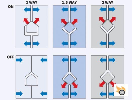
This differential is a bit complicated to explain, we will try to be as clear as possible. We start from an open differential with the satellite axle and its planetaries, but we will do something different: the satellite axle will have a little slack in the housing, where we will carve something like a triangle. On the sides of the planetariums, we'll place some friction discs attached to the differential housing, and sandwiched between them, some steel discs attached to the planetarium. Since the discs are intercalated, we will have to incorporate a pressure spring that engages them, so that the wheels get torque.
In this way, when one of the wheels rotates more than the other, a force is generated so that the wedge of the planetary discs will push the discs on both sides, locking the differential. These discs are nothing more than a clutch which, when engaged, work like a locked differential. In normal situation, when turning, the discs slide against each other allowing one wheel to turn faster than the other. As a video is worth a thousand images, here is one with the explanation.
Depending on the shape of the housing cut, we can talk about 1-way, 1.5-way or 2-way differentials. The 1-way differentials work only in acceleration. The 1.5 way differentials work in acceleration and very little in braking. 2-way differentials work equally well in acceleration and braking, and are not recommended on the road, due to the stability problems they pose when braking.
They are usually used in sports cars as rear differential, although there are some exceptions. Special mention deserves the Audi crown differential, used in some Quattro models, such as the RS4 or RS5. It is used as a center differential and is based on the same principle as the disc differential, with some slight variations, reaching in this case a TBR of 1.667:1.
Depending on the friction material of the discs, they can have different TBR. It can vary from 2:1 (33 %) to 400:1 (99.5 %), or even more. This type of differentials are used by BMW in their "M" vehicles, and in competition. I leave you a video where you can see the comparison between an open differential, another LSD at 25% (TBR of 1.667:1) and the disc differential. The disadvantage of this differential is that the coupling is somewhat rough and requires maintenance, due to wear of the discs. As an advantage, we can mention that its TBR can vary from 2 to 400, depending on the adherence of each wheel.
Viscous or Ferguson coupling differential
This is a series of discs, each coupled to a shaft - primary or input and secondary or output - and immersed in a viscous fluid, normally with a high silicon content. When the primary shaft slips, it begins to rotate at a higher speed, increasing the viscosity of the fluid, and therefore, coupling the discs, i.e., locking the differential. With this type of differential, the vehicle behaves as if it were two driving wheels, as it only locks and transmits force to the other axle when the primary axle slips.
It is usually used as a central differential and its TBR is variable depending on the number of discs, their material and size. If you have time and want to understand it better, I leave you a couple of videos of Lancia (part 1 and part 2), they used it as a central differential in their Delta and Prisma 4×4.
Rigid type differential
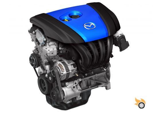
Although there is the epicyclic or planetary differential, which can also perform torque distribution (as in the Toyota Prius, to distribute the power of the heat engine between the electric generator and the wheels), I personally do not know of any vehicle that has a differential of this type as a drive axle differential. Therefore, we will focus on the Torsen type differential, widely used in many vehicles.
As mentioned, the Torsen differential (Torque Sensing) was patented in 1958, and its patent expired in 1978, twenty years later. When the patent expired, the design was released for anyone to use; although the owners of the patent registered the trademark "Torsen", so no manufacturer of differentials of this type can use this name. This is why you have heard of Quaife, Wavetrac, Eaton differentials... but they are definitely Torsen. Let's see how it works.
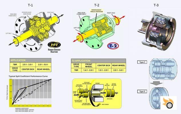
There are basically two types of Torsen differential: the T-1 and the T-2. The difference is that in the T-1 the satellites are placed perpendicular to the differential axis, while in the T-2 they are placed parallel. There are also the variants T-2R (for competition) and T3 (more compact) but they are just an evolution of the T-2.
What does the Torsen provide? While the other self-locking differentials depend on a condition to start working, the Torsen works continuously, making the torque transition smoothly from one wheel to the other. The coupling is rigid and continuous, so there are no discontinuities in its operation as in the disc or viscous. Maintenance in this type of differential is limited to changing the oil after the programmed interval. Remember that in the disc differential, it is also necessary to change the friction discs due to wear.
The T-1 has a rougher operation, although it withstands more torque than the T-2. For this reason it can have a TBR of 2.5:1 to 5:1. In contrast, the T-2 is smoother and quieter, making smoother and more predictable transitions. Its TBR ranges from 1.4:1 to 3:1.
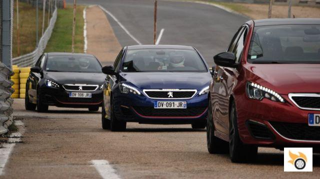
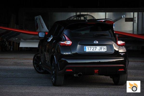
The T-3 has the particularity that it initially distributes more torque to one of the two axles. That is why it is used as a center differential, making an initial distribution 65:35 between the front and rear axle. Audi has used it a lot in its longitudinal engine Quattro models, but now has introduced the crown center differential, which we talked about before. Normally this manufacturer uses an open differential on the front axle, a T-3 as a central and a T-2 at the rear. A self-locking differential is not usually used on the front axle, as it would induce torque steer, with most manufacturers opting for an open one, although there are exceptions such as the Opel Astra OPC, which has a disc LSD. The Nissan Juke Nismo RS we tested last year suffers from this parasitic effect in the steering.
As a disadvantage, we have to mention the no grip condition (wheel in flight). In this case the Torsen differential behaves like an open differential. That is, it will send all the torque to the wheel that is in the air, losing traction. To avoid this condition, Wavetrac has designed a Torsen differential with preload, which avoids precisely this.
Active differentials
In recent times, electronics has invaded everything, and differentials could not be less. Let's list the three most important types of active differentials.
Haldex
The Haldex differential may be the most famous of them all. Basically it is a differential like a disc differential, with friction discs intercalated, where the locking is managed by a small oil pump that introduces or removes pressure to the discs, so as to lock or not the differential. This pump is managed electronically, therefore, we could define it as an electronically controlled electro-hydraulic clutch.
The Haldex clutch was the one that has democratized the all-wheel drive in vehicles with transverse engine. Remember the Volkswagen 4Motion or the Quattro traction of the Audi A3 and TT.
Like the viscous, the Haldex is used as a center differential, and the cars behave as two-wheel drive (usually front-wheel drive). When a low-grip condition occurs, using the car's sensors, the Haldex lock is activated, passing torque to the rear axle. In the first versions this transfer was done in a somewhat abrupt manner, requiring a noticeable slippage of the front axle to come into action. It is currently in its fifth generation, having refined and anticipated its operation, making it practically imperceptible to the driver when it comes into action.
Electronics with torque vectoring or torque vectoring control
There is another modality that is being imposed in the high range of high performance sports cars. This differential, quite complex and heavy, is a duplicate version of the Haldex, but to be used on the rear drive axle. On either side of the differential are discs, which in turn are connected to a valve and an electronically controlled oil pump. When the electronics consider that more torque is needed on the right wheel (left-hand corner, for example), it activates the valve on that side and the pump kicks in, sending more pressure to the discs on the right, causing more torque to be transmitted to that wheel. Exactly the same can be done with the opposite wheel. So it's like having two Haldex clutches, each connected to a half shaft.
These differentials are very useful, since you can regulate very precisely when to activate it and how much torque is sent to each wheel. On the other hand, the cost, weight and wear are points against them. It should also be noted that in very demanding operating conditions, due to the friction of the discs and the high oil pressure, they can overheat and stop performing their function, until the service temperature is recovered. You can see a video with this type of differential in operation below:
Virtual
Finally we have the virtual self-locking differentials. This is the cheapest version of an LSD, as it is based on an open differential and brake actuation. How does it work? Let's remember that the open differential had the disadvantage of sending more torque to the wheel that slides the most, just the opposite of what we want. By means of the electronics, this slippage is detected, and the brakes are activated only on the wheel that slips. Automatically the open differential will send more torque to the other wheel, as it offers less resistance than the one that is braked.
Its main disadvantage is that it produces more fatigue in the braking system, especially in heavy use. It is designed for a more sporadic use, saving the weight and consumption of the differentials of the types described above.
It is something very intelligent and economical, as it can be used in any current vehicle. In fact, when we see a vehicle with torque vectoring advertised - except for those that use an active differential - it is nothing more than what we have just seen: an open differential with limited slip through selective braking. This type is used massively in most vehicles of the SUV segment. You can see it in operation in the case of the Porsche 718 Cayman:
As a review, mention that selective braking can also be performed, even if we have an LSD, to accentuate the torque. This is used by Audi in some of its Quattro models.
So much for our review of this device that, as you have seen, is essential to have good traction in our vehicles, and compensate for the differences in rotation of the drive wheels. I know that we have left many details in the inkwell, but the idea was to have an overview about its operation and the different options offered by manufacturers to solve various situations that we can face, such as moving forward on snow, or get out faster from a curve on a circuit with full throttle.
In conclusion we can say that a good self-locking differential can make driving much more fun and effective than an open differential, which in the end is what we are looking for when driving. That's why we are pistonudos.